|
Recommended
ceramic tip alignment tool for this kit |
<<<<<<
MORE kits ..... view other available kits
>>>>>>
|
Recommended
ceramic tip alignment tool for this kit |
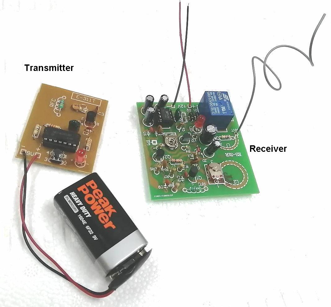
The kit consists of two separate units :
(1) a
transmitter & (2) a receiver
BASIC
OPERATION:
Pressing the tact switch on the transmitter, the receiver will respond by
energizing a relay (& light up the LED)
Releasing the switch, the relay on the receiver unit return to its inactive
state
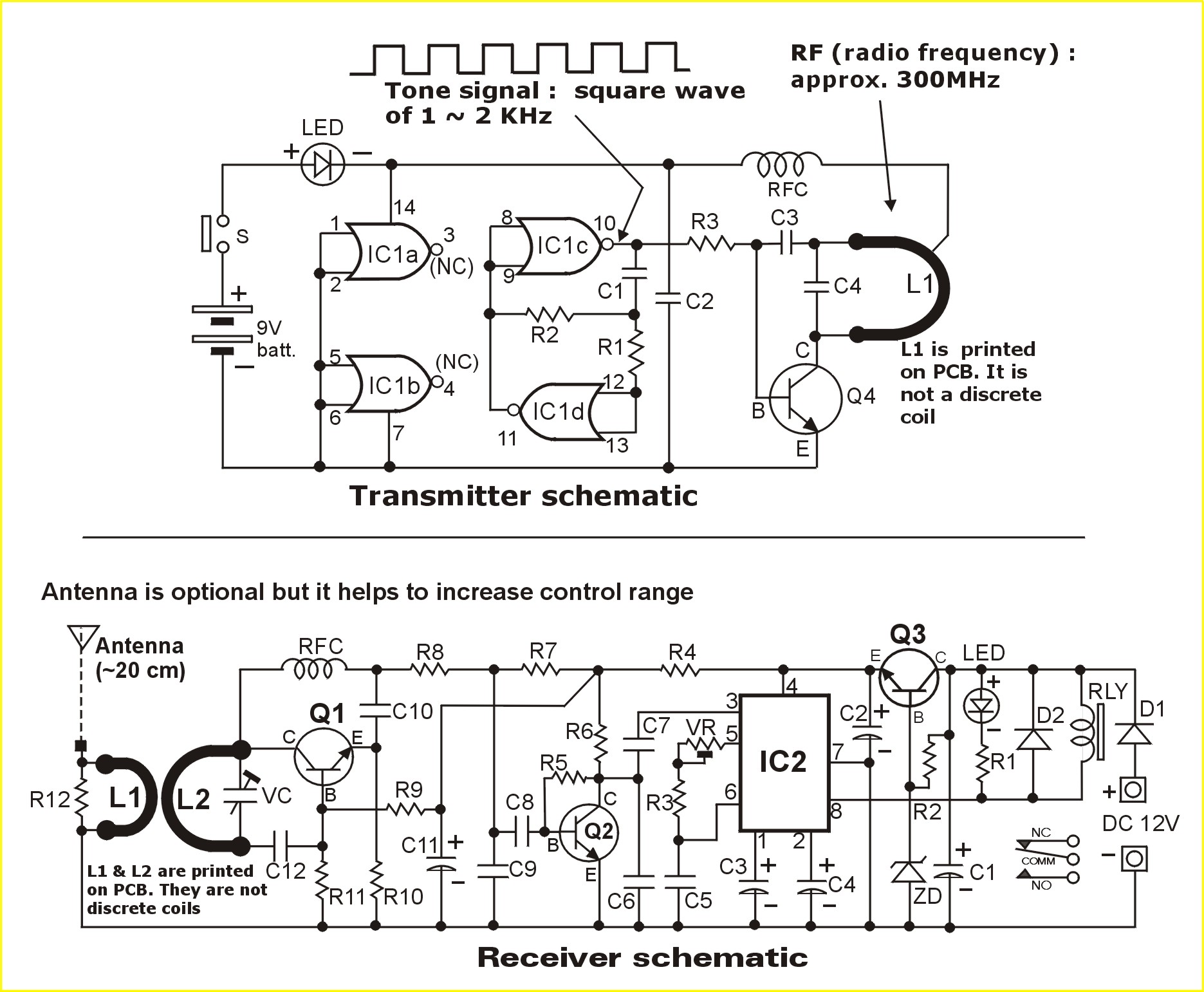
ABOUT THE TRANSMITTER:
The transmitter consists of 2 sections :
1) The AF section comprising logic gates IC1c & IC1d which generates a tone
signal with frequency around 1 ~ 2KHz.
2) The RF section : C4 & L1 & Q4 form a LC oscillator which generates a UHF
radio wave of around 300 MHz.
The RF signal is modulated by the tone signal in the OOK mode (ON/OFF Keying)
and then transmitted to the receiver unit located from a distance
ABOUT THE RECEIVER:
The receiver circuit is a simple super-regerative AM receiver which
has very high sensitivity.
The tone signal detected is amplified by Q2 and fed to the input of tone decoder
IC NE567 ( IC2)
The tone decoder compares the tone signal received (at pin 3 of IC2) with
PLL VCO frequency (pin 5).
If the frequencies of both signal match or close enough, output pin (No.8) drops
low & energizes the miniature relay (& illuminates the LED). Click here for
NE567 datasheet (pdf)
ALIGNMENT PROCEDURE:
Since
frequency counters are not available to most hobbyists, we simplified the
alignment procedure
so that it can be done without any instrument.
Step (1) : Powering up the transmitter & receiver units
Transmitter : Connect a 9V battery to the battery clip
Receiver : connect a stable DC 12V supply to the terminals marked+ 12V -
You may use batteries or a DC 12V adaptor (@200 mA)
Step (2) Adjustment of PLL osc frequency. Place the transmitter on top of the
receiver so that the
printed coils of both units come closest to each other.
Now press & hold the transmitter tact switch & slowly adjust the trim pot VR of
the receiver until
relay actuates & LED on. Press & release the switch several times to ensure the
relay responds promptly.
Step (3) Adjustment of RF frequency. Next, move the transmitter away from the
receiver so that
both units are approximately 1 m apart.
Again press & hold the transmitter tact switch & slowly adjust the VC (trim cap)
on the
receiver until relay actuates. To increase the control range : move the
transmitter further away & do a
fine tuning on VC.