Project  # PE-08
2000W AC Light Dimmer,  Temp  or 
Motor  Speed Controller
(AC 230V) 

  MORE projects
         

   Get
Price List


WARNING : This project is mains operated. Do not touch any part of the circuit when power is on. Electric shock can be fatal.
DESCRIPTION :  

This dimmer circuit can be used to control the brightness of incandescent light bulbs, the temperature of heaters & the speed of AC motors.  The max. controllable power is 2KW (i.e. 2000W)
* If the dimmer is being used over long period of time, we recommend   load power to be limited to 800W so that TRIAC is not overheated due to the small size of heat sink.

Schematic   Click on picture to enlarge


CONSTRUCTION

Step (1) : 
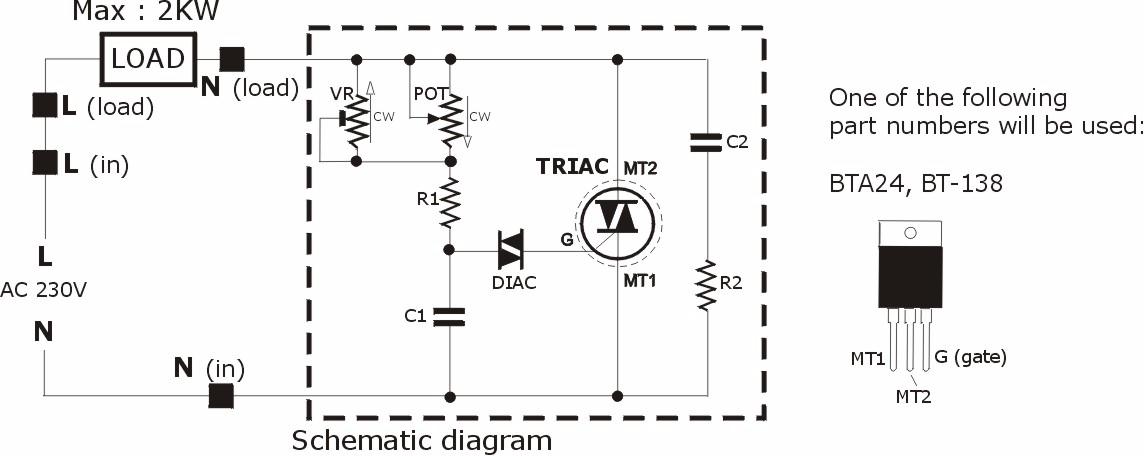
Mount the TRIAC on the heat sink using the mounting accessories provided. Apply small amount of silicon heat transfer compound (if available) on both sides of the mica to improve heat transfer. When done, check with an ohmmeter to ensure the center pin (MT2) of the TRIAC is fully isolated from the heat sink.

Step (2) : 
Insert & solder DB3 & all the resistors. Trim the leads with a cutter


Step (3) : 
Insert & solder the 0.1uF capacitors (2 pcs). Trim the leads with a cutter


Step (4) : 
Insert & solder the 2M Ohm trimmer pot (VR)


Step (5) : 
Insert & solder the 500K Ohm potentiometer (POT)


Step (6) : 
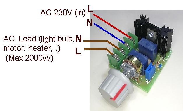
Insert & solder the 4-contact terminal block


Step (7) : 
Insert the TRIAC (with heat sink) and solder the leads then trim the leads with a cutter


TEST

Step (1) : 

Hook up the circuit below. DO NOT turn on the AC mains supply just yet.  You can use a incandescent light bulb (40~100W) as load for testing purpose.

Step (2) :  Turn the potentiometer (POT) fully counter clockwise


Step (3) :  Turn the multi turn trimmer pot (VR) fully counter clockwise

Step (4) :  Turn the multi turn trimmer pot  clockwise until the light bulb just starts to glow. This sets the minimum output for the dimmer


Step (5) :  Now turn the potentiometer (POT)  clockwise  slowly & the light bulb brightness should increase accordingly


CONNECTION OF MAINS INPUT & LOAD


CIRCUIT DESCRIPTION


Angle  Ф is the rotation angle of the potentiometer.   When potentiometer rotates counter-clockwise,  Ф increases
causing the shaded area to decrease and hence the load power.


PARTS LIST

P.C.B . Etched & drilled printed circuit board (included)
TRIAC BTA24   25A   (Datasheet)
or BT138 12A   (Datasheet)
DIAC DB3,   (Datasheet)  
Capacitors (C1, C2)  0.1 uF (# 104 or 100n) AC 275V capacitors
(blue or black color)
Potentiometer (POT) 

B500K (linear taper) 

Multi turn precision trimmer  (VR) 

2M Ohm (#205) 

Resistors

R1 --4.7K,  ( 1/4W or 1/6W)
R2 --100
Ω, (or 150 Ω)  ( 2W)

Heat sink,   4-contact Terminal Block,   Plastic knob,  3mm screw, insulator, mica (for mounting of TRIAC)

Buy the complete set of components for this project :
(all the parts in picture)