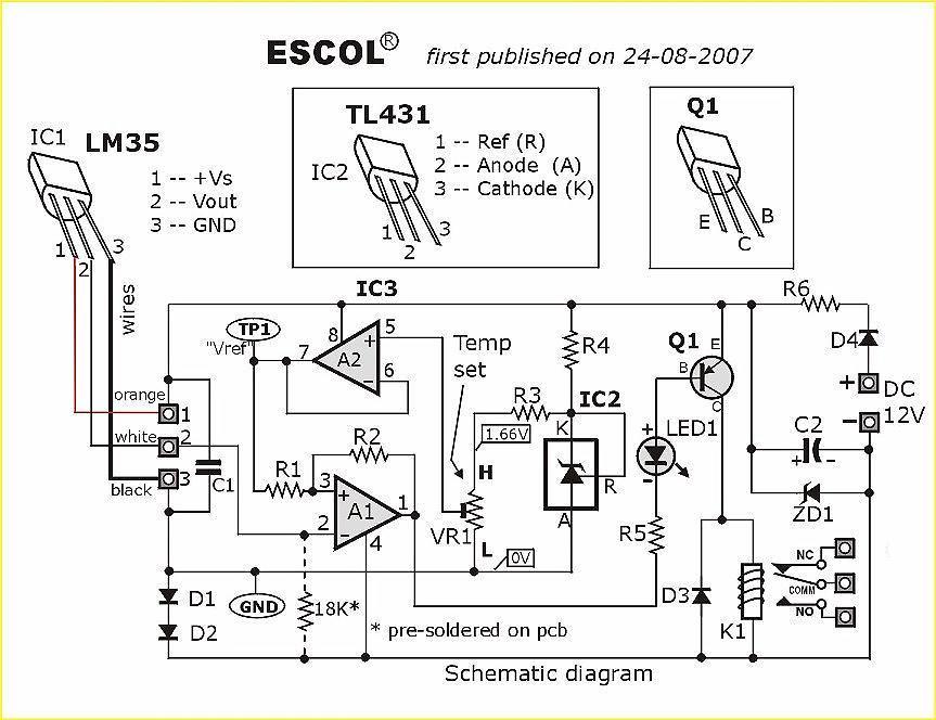
Project  # PE-03
 Precision Temperature Controlled Relay
using LM35 and TL431 
(0 ~ 100oC) 
 

  MORE projects      
   

 Get Price List


 PCB included


click on picture to enlarge

WHAT IT DOES  : 

In response to visitors requests, we have designed this simple yet highly accurate thermal control circuit which can be used in applications where automatic temperature control is needed. The circuit switches a miniature relay ON or OFF according to the temperature detected by the single chip temperature sensor LM35DZ. When the LM35DZ detects a temperature higher than the preset level (set by VR1), the relay is actuated.  When the temperature falls below the preset temperature, relay is de-energized. The circuit can be powered by any AC or DC 12V supply or battery (100mA min.) 
 
Remark :
 There are several versions of LM35 temperature sensors :.
    LM35CZ & LM35CAZ  (in TO-92 case) ---  −40oC to +110oC
    LM35DZ    (in TO-92 case) --------------    0 ~ 100o
    LM35H & LM35AH (in TO-46 case) ------  −55oC to +150oC

The one we supply with this project is the -DZ version with temperature detection range from 0 ~ 100oC.  

HOW IT WORKS : The heart of the circuit is the LM35DZ temperature sensor which is factory-calibrated in the Celsius (or Centigrade) scale with a linear Degree->Volt conversion function. The output voltage (at pin 2)  changes linearly with temperature from 0V  (0oC)  to  1000mV (100oC). This greatly simplifies the circuit design as we only need to provide a precision voltage reference (TL431) and an accurate comparator (A1 of LM358) in order to construct a complete thermal-controlled switch. The preset (VR1) & resistor (R3) from a variable voltage divider which sets a reference voltage (Vref) form 0V ~ 1.62V. The op-amp (A2) buffers the reference voltage so as to avoid loading the divider network (VR1 & R3).  The comparator (A1) compares the reference voltage  Vref  (set by VR1) with the output voltage of LM35DZ and decides whether to energize or de-energize the relay (LED1 ON or OFF respectively).  The purpose of R2  is to provide a bit of hysteresis which helps to prevent relay chattering.  Hysteresis is inversely proportional to the value of R2.  Lower value of R2 gives higher hysteresis.

Calibration :   No special instrument is required. The relay can be set to "trip" (change state)  at any temperature form 0 ~ 100oC.  For example: To set a 70oC trip point ( switchover temperature) :
  1. Connect a precision digital volt meter or multimeter across the test points "TP1" & "GND". 
  2. Slowly Adjust VR1 until you get a exact reading of 700 mV ( or 0.7V) on your voltmeter or multimeter.

Application example : Here is a practical example showing how the circuit can be incorporated in an automatic temperature control system which maintains the temperature of water in a container at  70oC.   Click here  for details


Thermostat1-sch.jpg (163609 bytes)
Click on picture to view the schematic

Click on picture to view parts layout 


PARTS LIST


IC1 :
   LM35
DZ  Precision Celsius (Centigrade) Temperature sensor 

IC2 :  TL431  +2.5V precision voltage reference 

IC3 :  LM358  Dual single supply Op-amp. 

LED1 -- 3mm or 5mm LED 

Q1 -- General purpose PNP transistor ( A1015,...) with E-C-B pin arrangement)
 
D1, D2
  -- 1N4148 silicon diodes (or 1SS133)
D3, D4 
-- 1N400x (x=2,,,,.7) rectifier diodes

ZD1 --- Zener diode,  13V, 400mW

Multi-turn Trim pot   :  2KΩ   (# 202 or  2K)
  (for Temperature setting)


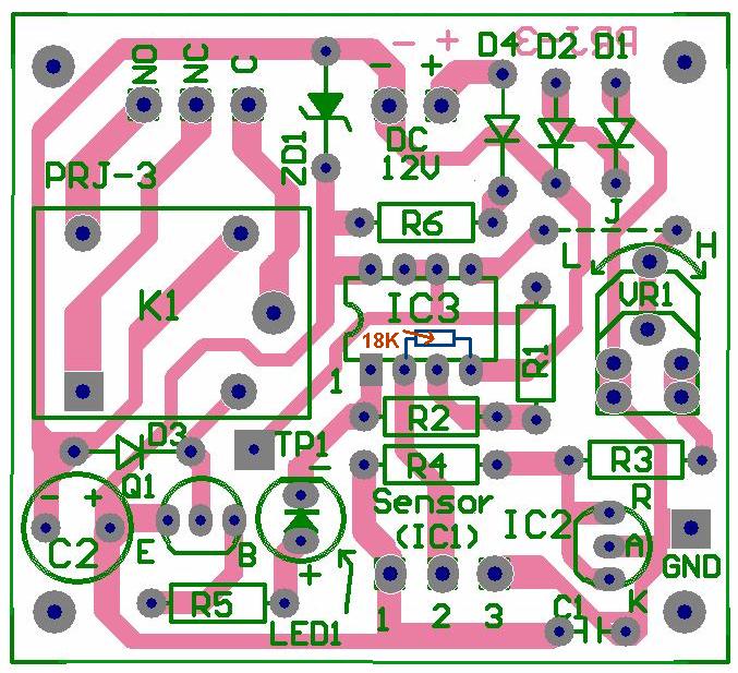
Printed circuit board  --  1 pc.


Resistor  : ( 1/4W or 1/6W)
  • R1 -- 10K   
  • R2 -- 4.7M
  • R3 -- 1K
  • R4 -- 1K
  • R5 -- 1K
  • R6 -- 33Ω
  • * 18K 1/6w (pre-soldered on pcb)

Capacitors :

  • C1  -- 0.1 µF ceramic or mylar cap
             (# 104 or 100n)
  • C2  -- 470 µF or 680 µF electrolytic cap.  (16V min)

Miscellaneous items :
 
8-pin socket -- x 1 pcs
 Miniature relay -- DC12V  SPDT, Coil=400
Ω or  higher